Westerbeke 12.6BTD genset - starting issues


hotdog1948

New member
My 45 Yacht Westerbeke 12.6 BTD has been running fine for 2 years, but will not now start.

When trying to start, it blows the 8A fuse in the circuit.

I have replaced the fuel solenoid, and the battery, but the problem persists. After a lot of diagnosis, I have concluded the only option left is to replace the starter. Unfortunately, the starter is on the side of the generator against the forward engine room bulkhead. There is only about 12" of room to work in. A Volvo tech who has replaced the genset starter on another 45 Yacht said that it can be done without pulling the genset out. He said you can even do it without removing the enclosure sides, except for the top and the enclosure wall on that side of the generator. The enclosure wall on that side of the engine can just be removed and set down against the bulkhead there.

Three questions -
1. Has anyone replaced the genset starter on a 45 Yacht, and do you have any suggestions about how to proceed?
2. Can you confirm that the starter part number is 030593, and is it ok to purchase the Mitsubishi starter with same part number? (Several sources offer Mitsubishi starters with that part number, and list several gensets that it should work with, but they don't list the 12.6 BTD. I suspect any Mitsubishi 030593 starter will work.)
3. Should the voltmeter display a voltage when no button is pressed? (See background discussion below for clarification on this question.)

Thanks for any help,
Steve

* * * * *

Some Background:

The symptoms are quite unusual. The starter will engage and turn the engine. It will almost start, but then blow the fuse and stop. (It does this even when the leads from the alternator R terminal are disconnected.)

Schematics show that there is a circuit breaker, emergency stop switch and an 8A fuse in series with the pre-heat and start buttons. Pre-heat and start solenoids are downstream of the buttons.

Circuit breaker and emergency stop switch are fine.

Historically, the voltmeter always displayed ~14V, even if not connected to shore power so the dedicated 6A charger is not supplying the battery. (I have pics from 2 years ago that show the 12V even when not connected to shore power.) Pressing the pre-heat button would cause the voltage to drop some. Pressing the start button would reduce the voltage further. This is consistent with how a Westerbeke 30B Three auxiliary would start on a sailboat I used to own. It had a key. Turn the key, the voltmeter would come on and display 14V, etc.

On the 45 Yacht, there is no key for the genset; so it always displayed voltage on the meter. BUT NOW, no voltage is displayed on the meter, even after replacing the fuse, checking the breaker not tripped, and the emergency stop switch on. When pressing the pre-heat, the voltmeter is activated and it displays a voltage. Then, while holding the pre-heat on, pressing the start button causes the voltage to drop some and the engine to turn over and attempt to start. It then blows the fuse and stops. The weird thing is this behavior IS CONSISTENT with the Operators Manual, which states that pressing the pre-heat button will activate the voltmeter. This behavior is also consistent with all of the circuit drawings I've found, which show that the voltmeter is in series only with a circuit breaker, the emergency stop switch, the 8A fuse, and the two buttons (pre-heat and start). With no buttons pressed, the meter should not be energized at all. In parallel is a connection to the genset alternator R terminal, but that should not provide a voltage unless the engine is running. (I checked and there is no voltage on those leads or on the alternator R terminal for those leads when at rest. There is 12V on the alternator B lead that comes from the starter, and is just an extension of the battery lead.)

I wonder now if the previous behavior was not normal. That is, I wonder if the voltmeter should only register a voltage if the pre-heat is pressed. Can anyone confirm this?
 
Had something similar on westerbeke 7.6btd. Blowing 8a fuse. Turned out to be water temp switch shorting to ground.


Sent from my iPhone using Tapatalk
 
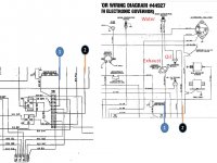
Well, that's a great suggestion. Thanks for that! From the drawings, there are 3 sensor switches in series - exhaust temp, water temp and oil pressure - and together they are in parallel with the pre-heat button (aka the "run" button). The pre-heat button activates both the pre-heat solenoid and the fuel-pump solenoid. Either path -- through the pre-heat button or through the 3 switches -- will activate the fuel-pump "run" solenoid. The pre-heat button also activates the pre-heat solenoid to activate the glow plugs, but they are disengaged as soon as you release the pre-heat button.

Exhaust temp and water temp are normally closed. Oil pressure only closes when minimum pressure is reached. During start sequence, the oil pressure switch is the only one that is open. When sufficient oil pressure is detected, the switch closes and you can release the pre-heat button. The circuit remains completed because temperatures are still very low, so the fuel pump continues to operate. If while running, exhaust or coolant temperature gets too high, or oil pressure gets too low, that breaks the circuit, de-energizes the fuel pump, and the engine stops.

Possible that one of those switches is shorting to ground when energized, which would cause the fuse to blow.

I'll definitely check that out. Hopefully save a bunch of bloody knuckles!
 
Schematic (I'm looking at) shows the 8A fuse on the panel and 20A breaker on the Gen. The 20A feeds the 8A and the 8A is there to protect the panel. If anything in the panel or relays starts to draw more current, it will blow the fuse. Things are

All panel gauges and hour meter
Start and Run relays
 
Thanks to Wilks for the clue to check the Coolant Temp switch!


I have verified that the Coolant Temp switch was grounding out, just as Wilks suggested.


I disconnected the leads and jumped them together. Engine now starts just fine, and the fuse no longer blows. Yay! This also tells me the Starter is good, and most likely the Starter solenoid is, too. The start sounds clean and the engine fires up quickly. Oil pressure climbs rapidly.


BUT (why is there always a but?), now the engine will only run as long as I continue to depress the Pre-heat button. When I release that button, the voltage drops to zero and the engine dies. So, as unlikely as it seems, something else is also wrong.


The genset ran just fine until it didn't. It's still a puzzle.


I have verified that two of the remaining switches (Oil Pressure, Aux Oil Pressure) are good. (The Aux Oil Pressure switch is normally closed, but in the drawings it is not connected to anything except an empty terminal on Terminal Block 2.) I tested them also using jumpers. I disconnected the normally open Oil Pressure switch and jumped the leads together. I also disconnected the normally closed Aux Oil Pressure switch. Disconnecting these switches had no effect on the engine - it starts and runs until I release the Pre-heat button. (It is not clear what the Aux switch is supposed to do, since it is not connected to anything, according to the drawings.)


I have not yet tested the Exhaust Temp switch; if it has failed open, it breaks the circuit which would deactivate the Run solenoid. So that is still a candidate, and that would explain why the engine stops when I release the Pre-heat button. I hope to test it tomorrow.


Thanks, also, to AllDodge for the suggestions re panel gauges, etc.

I have replaced the Pre-heat solenoid, which I believe also serves as the Run Relay (K2 in the schematic). I should probably verify that.


It is possible that something on the panel has failed. I will focus on that if the Exhaust Temp switch passes muster.


I have verified that the engine-mounted 20A circuit breaker is not tripping, so it seems unlikely that something in the panel is grounding out. The meters are all in parallel with the circuit that energizes the Run relay, so a failed meter would not likely cause the engine to stop.


It is also possible that either the Stop switch or the Emergency Stop switch has failed open. That would account for the engine stopping when I release the Pre-heat button. I need to check those, as well, and hope to do that tomorrow.


It seems also possible that the alternator is not providing 12VDC to the fuel pump, as it is supposed to do when the engine is running. I need to check that, as well, but I need a third arm for that!


There is also a Remote Panel (in the guest berth) that has switches and a voltmeter. Could be something failed there. However, they are all in parallel with the primary panel. Since the fuse does not blow, I don't suspect that panel.


Thanks again for the suggestions.
 
As a non-expert
The schematic leads me to believe the switches (coolant, oil pressure, exhaust) are normally closed and apply a ground to one side of the run relay. If any are disconnected then that removes the ground and the relay de-energizes
 
Mostly correct, AllDodge. Thanks for the attention to detail!


The switches are connected in series between the battery +12V post and K2 Run Relay terminal 86 - the high side of the solenoid. All 3 are closed when the engine is running. If any opens up, they cut the voltage to the K2-Run Relay, which cuts power to the fuel pump.


The Coolant and Exhaust Temp switches are normally closed. Oil Pressure is normally open; it closes when sufficient oil pressure is present for the engine to operate (usually 5+ psi).

All 3 must be closed to maintain voltage activating the K2 relay after releasing the Pre-heat button.


The switches can be tested by removing and joining the leads with jumpers. If the engine starts and runs with jumpers in place, that demonstrates that a switch was bad.
 
Have electrical background but next to no one knows how to make a good schematic other then the Navy. The Westrbeke drawing is hard to follow and I'm seeing all the switches are together

west.jpg
 
Roger Navy schematics, AllDodge!


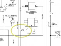
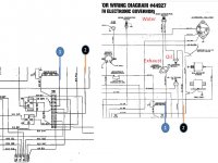
There is a symbol on the schematic that nobody seems to recognize. Circled in yellow in the pic. Might help to understand what that is. I suspect it is some sort of voltage-controlled valve, but I haven't found that symbol anywhere on the Web. On the diagram, that symbol sits in the circuit that should supply the fuel pump. Plausible that is bad, but seems unlikely since the engine starts and runs. That symbol might also refer to the Actuator (part of the governor system). I don't yet know how to test it, so may just replace it and see if that makes it well.


Using jumpers, as appropriate, I have verified that it is not the circuit breaker, or any of the safety switches (Emerg Stop, Stop, Coolant Temp, Oil Pressure or Exhaust Temp switches). I have also verified that the alternator produces +13V when the engine is running (as long as Pre-heat is held down).


About the only thing left is a diode (which I can't seem to locate). It could be burned out, which could open the circuit when Pre-heat is released. It shows up as p/n IN4002 between Overspeed board (the electronic governor) and +12V. It is also available on the Westerbeke website.


The Overspeed board also apparently has a normally closed switch built in. But that board is always in the circuit, so it seems if it was bad, the engine shouldn't start at all.


It is still puzzling that the Voltmeter does not show 12V at rest like it used to. From the schematic and diagram, it should never have shown voltage unless Pre-heat is down or engine is running. BUT, it used to, and it always started and ran like it is supposed to. So might be something to do with that.


I'm rapidly running out of ideas.

8.0-15.0_btdc_eg_src_rev b(44927)_cropped_circled.jpg
 
I look at that symbol as like a butt connector or the like (quick connector). Just connects all 3 together, but may not be directly at the pump
 
Butt connector makes sense, great suggestions. I'll quit looking for something fancy with a filament!


I should receive the 3 switches tomorrow and hope to get them installed and tested. Will report out.


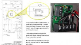
In the meantime,... The schematic side of the drawing indicates that the three switches (Coolant Temp, Oil Pressure & Exhaust Temp) are in series with the Overspeed board. (See pic).


That board has a normally-closed switch in it (in the schematic side of the drawing). I'm guessing it is a "latch" that should remain closed after the Pre-heat is released. If it doesn't remain closed, that would account for the engine stopping.


Unfortunately, that board is labeled with two different part numbers and neither is in the Westerbeke catalog. So, I'm going to have to call them for pricing.


overspeed.jpg
 
UPDATE

An email to Westerbeke via their website Contact Us page elicited a useful reply.

The Overspeed board is in "Service Bulletin 241 diesel overspeed board.pdf"

P/n 049520 PC Board Assy,Overspeed 12VDC.
Price: $123.40

If replacing the safety switches does not solve the problem, it looks like this Overspeed board will be next on the target list.
 
All 3 switches* installed and tested - No Joy. So I've ordered the "Overspeed Board" part that Westerbeke identified in their email. Install should be easy (4 connections to a screw terminal block) and no calibration required. Fingers crossed.

*I had verified that the Coolant Temp switch was bad and grounding out, which caused the fuse to blow. This is a common problem. So 1 out of 3 was bad. I'll keep the other two as spares. The schematic shows that the Overspeed Board is in series with the 3 switches. Also, one puzzling symptom is the fact that it does not now show +12V on the meter when battery is connected, as it used to. That may be a symptom of the Overspeed board failure.
 
UPDATE
Overspeed board was back-ordered at Westerbeke. Arrived yesterday (only about 1 wk delay). Box included Service Bulletin #241 which indicates the board was added to the system in 2004. It also states the board contains a switch that is in series with those three "Safety Switches." Installed today. No joy. One symptom that is increasingly drawing my attention is the fact that the Voltmeter does not register voltage at the "Generator Battery" (either in the remote panel in the Guest Berth, or on the Control Panel mounted on the genset). I believe that is trying to tell me something.

Reviewing the schematic, looking upstream suggests I need to test whether that board is actually receiving. I'll try to get that done today and report back.
 
Last edited:
Turned out not straightforward to test if the board is receiving power.

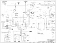
From the schematic, the alternator "R" terminal is connected to the output side of the K-2 Run Relay, and it is directly connected to power the Fuel Pump. Can someone explain how that terminal plays in the circuit? Thanks.

8.0-15.0_btdc_eg_src_rev b(44927).jpg
 
Your drawing is unreadable, to small. The good thing is I have the same diagram
Did I mention this drawing is crap...... and my opinion of how it works

Pin 30 of K1 and K2 have full time 12V
When K2 energizes it supplies power to fuel pump and ALT. When motor is running the ALT is powered to charge the bat and keep everything running

Pin 85 (coil) comes from the over speed board and is what keeps it energized by applying a ground. Pin 85 (other side coil) gets power thru the Aux oil pressure switch from TB2-8 which comes from the 15 pin connection (don't know what it is yet, part of main connector harness to panel)

Gen stops by STOP switch may remove power to TB1-2 to same 15 pin connection
 
Last edited:
Hi Dodge,
yep, I've been studying this drawing till I see it in my nightmares!

With your comment I am now able to decipher the plug in the lower left-hand corner of the drawing. I now see that it corresponds to the circled digits in the schematic section.

The Fuel Pump is clearly energized from Pin 87 on the K-2 Run relay. (The same line that energizes the "R" (Rotor) terminal on the alternator.) Pin 30 on K-2 Run relay is always hot (+12V). Pin 86 on that relay gets +12V when the Pre-heat is pressed, and the Fuel Pump starts running. After engine starts, should be possible to release the Pre-heat and should still see +12V at Pin 86. That +12V should be coming from the output of the O'speed board. Since the 'safety switches' and the O'speed board are all new, and the engine runs, that suggests the K-2 Run relay is good. It seems the key is something is drawing voltage off of Pin 86 of K-2 when the Pre-heat is released.
 
Last edited:
I can't read the drawing either, but from what you guys are saying it seems like there should be some type of "seal" circuit that keeps power on Pin 86 of K2 when preheat is released. Is there a temperature switch parallel to the preheat, that would seal the circuit in?? I've done a lot of design and trouble shooting of circuits like this, that's usually the way they're set up. Hope this helps.
 
Appears the stop switch is NC and what supplies power to the pre-heat.
The pre-heat when held supplies power to the start switch

The other coil side of K2 goes to TB1-2 and then to pin 1 of the 15 pin connector. Would need to find out where the 15 pin connector goes to, and my guess is it goes to the voltage regulator

The stop switch removes main power to both K1 and K2 pin 30 (main feed)

Pic from previous posting
west.jpg
 
Back
Top