
You are using an out of date browser. It may not display this or other websites correctly.
You should upgrade or use an alternative browser.
You should upgrade or use an alternative browser.
Westerbeke 12.6BTD genset - starting issues
- Thread starter hotdog1948
- Start date


Docter's Office
Member
I had the 1 cent diode blown that bridges terminal 2 and 6 on TB2. Similar issues. Took forever to track it down and that's all it was has run perfect since.
hotdog1948
New member
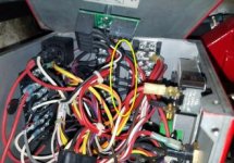
Thanks for that datum, Docter! That's very encouraging because I'm running out of options, otherwise. Part supposed to be delivered tomorrow. Since I didn't have sense enough to order that part when I ordered the Overspeed board, that $5 part cost $15 to ship. And I had to sign for it! It's on Slide 1 in the sequence that AllDodge just posted. Here's what it looks like under the rat's nest that's inside the control box - circled in yellow.

Attachments
Docter's Office
Member
That looks to be it. I soldered the u shaped terminal blades along with some wire to the ends of the diode so I didn't have to try and position it in the same place under all of the other wires. Make sure you take note of the direction of the current (match the lines on the diode) and that the new diode goes the same way. Good luck.
hotdog1948
New member
That's good gouge, thanks!
hotdog1948
New member
Replaced the diode. No joy. Same symptoms. Starts and runs just fine until I release the Pre-heat switch.
It was a reasonable suggestion, Docter. I do appreciate it. Whatever is going on, it's subtle.
I'm down to the short list of possibilities. Next up: A bad "K-2 Run Relay."
The schematic identifies the relay, but nothing on the Westerbeke parts list or on their website is identified as a "Run Relay." The term "Relay" only shows up 3 times in the Service Manual and 2 of the 3 times are on the diagram we're looking at. The third reference just says "Check the K-2 Run Relay."
I wonder - Is the K-2 Run Relay integral to the Starter Solenoid?
Also - what does the open circle (indicated by yellow arrow) represent on the schematic -- see image? The closed circle (green arrow) indicates that there is a connection. No circle means there is no connection when two leads cross each other on the schematic.
AllDodge
Well-known member
I do not think that K2 is integrated with the starter solenoid, at least not on the diagram I have.
Can you pull back so we can see where the connection is?
The diagram leaves a lot to be desired and I just don't know what a open circle would be. WB shows no connection by just crossing lines, and shows a connection with a dot. Maybe the circle means something but right now just don't know
Can you pull back so we can see where the connection is?
The diagram leaves a lot to be desired and I just don't know what a open circle would be. WB shows no connection by just crossing lines, and shows a connection with a dot. Maybe the circle means something but right now just don't know
hotdog1948
New member
The connection in question is located inside the circled area on the schematic. I suspect the open circle means the connection is contingent on something else, but not clear from the drawing. Glad I'm not the only one having trouble making sense of it!


hotdog1948
New member
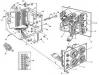
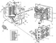
I'm working down another path at the moment. I believe now that the "K2 Run Relay" is located inside the Control panel box. Picture and drawing from manual below. The relay in question is in the back upper left corner of the box; part No 29 in the dwg. Does that seem plausible? I suspect since I've replaced everything in the circuit up to that relay, seems like the next logical thing to try. Here's the theory: The voltage required to close the relay is supplied directly from the battery. BUT, the voltage to hold it closed after the Pre-heat is released is supplied by the Overspeed board. If relay is bad, it may not hold with voltage supplied by Overspeed board. That would explain symptoms. Seems worth a try. I'm waiting now for Westerbeke to confirm that relay is K2 Run Relay.


Attachments

hotdog1948
New member
I believe the "Remote Connector Pins" mentioned on the diagram refers to the connector for the harness between the engine and the Control Panel box. It's where the cables exit the box near the relay in question.
hotdog1948
New member
Any idea where the other relay is located? There is only 1 relay in the Control Panel box. And that's the only relay listed on the official Parts list for this model. But the diagram shows 2 relays K1 and K2. So, I'm guessing the K2 Run Relay is the one in the box. But that's a guess based on the time-tested "grasping at straws" method.
hotdog1948
New member
Good call. In the schematic there are two Yellow wires with Red stripe connected to the Starter Solenoid. One Yel/Red wire in the schematic is not used in a genset with electronic governor (as this one has). The other connects to the K2-Run Relay.

hotdog1948
New member
You're right. I misread the drawing. Good catch.
That Yel/Red wire connects the Start Solenoid to the K1-Start Relay. So that suggests the relay in the upper far left corner of the Control Box is the Start relay, not the K2-Run Relay. Hmm.
The colors of the connections to the device in the picture correspond to the colors in the schematic for K1-Start. One of the red lines comes from terminal 1 of Terminal Block 1. That line is clearly visible in the picture. The second Red line from that relay in the picture wraps around Terminal Block 3 and apparently connects to something beneath the relay. So, perhaps there is a second relay in the box mounted beneath the first. The drawing shows only 1 relay in the box, but there appears to be room beneath that relay for another, similar relay. I've asked Westerbeke to locate that relay for me, but I'll investigate further when I get a chance.
hotdog1948
New member
hotdog1948
New member
Now that you mention it, in this image you can trace the violet wire from where it connects to a device below the K1-Start Relay to terminal TB2-6. From the Parts List, it should have the same p/n as the K1-Start Relay.
BTW - Westerbeke responded and pointed me to the ambiguous drawing that we have already looked at. They just said the drawing might be helpful. They also pointed me to a service provider. So, not much help there.

BTW - Westerbeke responded and pointed me to the ambiguous drawing that we have already looked at. They just said the drawing might be helpful. They also pointed me to a service provider. So, not much help there.