Westerbeke 12.6BTD genset - starting issues


I finally got a weather break and managed to remove/replace the K2-Run-Relay. No joy. Same behavior as before.


I also noted that the voltage comes up to ~13V when the engine is running. That tells me the alternator is working.


The Start and Run relays have the same part number. I plan to test the relay that I removed and (presuming it is good) replace the Start Relay with it as an act of desperation. I'm running out of actionable ideas -- except replace the starter.


For reference: Replacing K2-Run_Relay took about 2 1/2 hours

Part of the time was me looking for the right tools to get access to the nuts beneath the rats nest. A very long needle-nose pliers worked, along with some long skinny fingers.


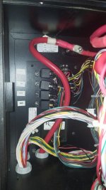
The K2-Run-Relay was located in that far lower left corner, below the K1-Start-Relay. Had to remove the top, front and port side of the genset enclosure, then remove the top and front panel of the Control Panel box. Finally had to detach the K1-Start-Relay and Terminal Block 3 and move them out of the way to gain access to the nut that secures the K2-Run-Relay to the enclosure. Took about 10 minutes to access and remove the relay, less than a minute to disconnect it and connect the replacement, and about 2 hours and 15 minutes to put it all back together. Bottom line: the box was not designed for maintainers.

 
Like you, I'm running out of ideas. Sure wish the schematic was readable to a normal human and not one which requires schooling with WB
 
I am determined not to replace the starter unless TINA (there is no alternative). Reviewing the schematic yet again, it would appear that if the Stop switch on the remote panel is defective, that might account for the behavior. That remote Stop switch is in parallel with the Pre-heat switch on the main panel. As long as Pre-heat is closed, the engine should start/run as it does. If release the Pre-heat, and if the remote Stop is open, then the engine would stop. I'm going to walk down this path for a while.

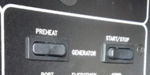
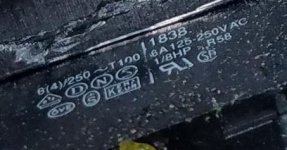
Of course, nothing is ever easy. Pictures show the front START/STOP and back of the snap-in switch on the remote control panel, with markings that should help identify the part. Relevant markings are 1838, R58 and 6(4)/250~T100. Basically it's a SPDT switch with one side momentary ON; center position OFF; other side momentary OFF. This appears to be a very unusual configuration. I find numerous (ON)-OFF-(ON) type rocker switches where the () represent momentary states. But I have found any that conform to what is needed: (ON)-OFF-(OFF). And I'm not seeing a way to wire up a switch that is (ON)-OFF-(ON) to achieve the required functional configuration.

Genset Remote ControlsBack-side of Start/Stop switch, remote panel
 
Last edited:
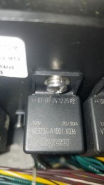
Discovered a relay labeled GEN in the panel behind the Start/Stop switch. Research determines it is a Bosch type automotive relay with two 87 terminals. 87a is NC. 87 is NO. When activated, the relay will break the circuit connected to 87a. Diagram in the 45 Yacht Wiring, Plumbing and Fuel Diagrams pub #42926 shows this relay terminal 87a connected to the Start/Stop switch on the Stop side. Note the naked 87 terminal not connected to anything in the picture. This is encouraging. I plan to replace this relay next. Hypothesis is that the NC circuit has failed open -- possibly when the genset blew the fuse.

20210217_160052_.jpg 20210217_160138_.jpg
 
Last edited:
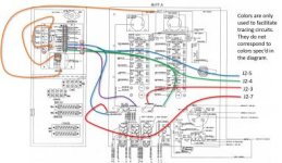
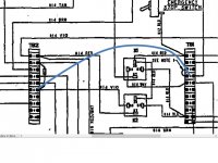
Replaced the GEN relay. No joy. Tested the OEM and it is good, so will keep it as a spare. Trying to make sense now of the wiring in the control panel. I still believe the problem concerns the remote panel, but that is a Formula issue, not a Westerbeke issue. Or rather, it's the interface between the two that is my focus right now. I'm tracing the wiring on this diagram (may be too small to interpret). It's from the Formula wiring book. There should be 12V on pin J2-5 (the blue line), which would put 12V on the center pin of the Sttart/Stop switch and on the Generator Battery voltmeter.

I am not seeing 12V there, and the voltmeter shows zero. So I believe the problem is there. That voltage should arise from the Westerbeke control panel. So that's where I go next!

img20210217_17472572_labeled.jpg
 
Try clicking this version of the image as a pdf file, it's the diagram without the colored overlay. I'm particularly interested in where the J2-5 connection might come from.

My failing memory was that the Voltmeter on the Remote Panel (in the guest berth) should show ~13V when all is at rest. When you press Pre-heat, the volts would drop. Press Start and volts drop even further as the starter turns over the engine. This is unique to the wiring in the 45, and is different from the way the normal Westerbeke Remote Panel works (per their manual). I'm convinced that the reason the remote panel doesn't work is related to the reason the engine won't continue to run. The fact that the Remote Panel voltmeter is showing 0V is trying to tell me something.

Referring again to the Westerbeke schematic, it would appear that the 12V on J2-5 in the Remote Panel comes from Terminal Block 1 by way of the 15-pin connector in the back of the engine-mounted Control Panel. A simple break in the circuit there could account for the behavior. I have no theory about how such a break could occur, but I think I can get to it, so tomorrow I'm going to see if there's +12V there.

I believe J2-5 provides +12V to the Remote Panel, J2-4 will service the 3 safety switches from the Remote Panel, J2-3 will service Pre-heat, and J2-7 will service Start.
 
Last edited:
This discussion has nothing to do with the TB1 circuit board showing in post 46

Scary part - Think I'm starting to understand the WB drawings
Best to use what I call logic schematic. It shows a logic connection and not the exact individual wire to wire connection

Each remote panel is in parallel with panel on GEN. Doing something on a remote panel is the same as doing it at the GEN. Only thing that can cause an issue is if a connection or switch becomes broken or shorts

Battery power to main breaker, to 8A fuse, to stop switch thru to preheat switch

Preheat applies power to TB2-2 thru Diode to TB2-6 to K2-86 (run relay)
K2 energizes and applies power to fuel pump, fuel solenoid, all gauges, ALT (terminal R), LED and to Start switch

Oil pressure switch - NO
Water temp switch -NC
Exhaust temp switch - NC
Pressing the Start switch bypasses all the above switches and applies power to K2-86

Once GEN starts and oil pressure switch closes, power is supplied thru Exhaust, Water and Oil pressure switches which are daisy chained to K2-86 to keep energized
Any of the GEN switches can de-energize the K2, along with pressing the stop switch by removing power to K2-86
Power is maintained to the switches from TB1-4 (jumped to TB1-3 only if 2nd remote panel is installed) that are spliced from splice connection J2-2 and J2-11

The boats breaker panel should show 12V full time, but the GEN panel should only show 12V once the GEN starts

Main power to the remote panel comes from TB1-2 and spliced to J2-1 (Red/Vio) and J1-4 (Brn)

I think there is something wrong with one of the safety switches
I would jump between TB1-4 to TB2-6. Doing this will bypass all the safety switches. If it continues to run then its one of them

Switch bypass.jpg
 
Hi Bob,
Thanks for taking the time. I know what you mean that it's scary to think we might be starting to understand this. You realize that we're alone in the universe, right?


The teeth-gritting, grrrrr part is that I have already changed out all 3 of the principal safety switches (Coolant Temp, Oil Pressure, Exhaust Temp) and I have jumpered the pins on the Aux Oil Pressure (NC) switch, as well. No joy. I also changed out the O'speed board and the diode. I may try your suggested jumper just to confirm that none of the new switches is bad.


I concur that something is causing the K2 to be de-energized so the devil lives in that circuit.


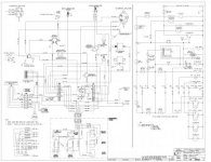
Question - how did you identify the "J1" and "J2" connectors? I'm not seeing those connector labeled on the diagram (below). I see the 15-pin connector on that diagram, but I don't see where it's labeled "J2." The "J2" connector identified on the Formula Remote Panel diagram has a lot more pins.

8.0-15.0_btdc_eg_src_rev b(44927).jpg
 
HI Steve
I'm using J1 as the remote panel and J2 as the 15 pin connector

The light bulb moment was when I looked closer at what I'm calling the logic diagram, which is the right side of the drawing posted (Still unable to read yours). The components can be listed more then once but they provide detail of how things work. Note how the power feed comes from TB1-4 to TB2-6 when Preheat is held in. The Preheat is bypassing the switches.

Saying it dies when Preheat is released means there is a broken connection to me
 
Ok, I can work with that. And I agree in principle. The problem must be somewhere in that circuit in series with those safety switches. Since I have replaced the switches, O'speed board and diode, I conclude the problem must be upstream from the switches.


Referring to your diagram, because the engine starts and runs with Pre-heat held down, the problem must be downstream of the primary Stop switch, somewhere between the primary Stop switch and the remote Stop switch, which is connected via your JP2 pin 1 to TB1-2; i.e., between TB1-2 (J2 pin 1) and TB1-3/4 (J2 pins 2 &/or 11).


Lots of pins, could be a bent pin in that connector, or a wire broken off at that connector. Dollars to donuts it's going to turn out to be something stupid like that!


Anyway, that's where I hope to look for a broken connection today.
 
Yeehaw!!! Success.

Only took 3 months.

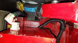
I discovered a special plug attached to the 15-pin plug on the back of the Control Panel. That plug has a jumper in it and is intended to allow disconnecting the Remote Panel. Plugged it in, the engine starts up and runs just fine. Closer inspection of the cable notes undocumented fuses (seen in the pic below). One on the Red line and one on the Green line. 3A fuse on Red line was blown. I don't have a replacement handy, so will take care of that tomorrow. But that would seem to be the issue.

Pic shows the jumper plug attached now. Also visible are the 2 undocumented yellow fuse holders in the circuit.

Thanks to Bob (AllDodge) for sticking with me! I owe you a beer Bob.

20210301_173340_.jpg
 
I believe the 3A fuse blew in the course of trying to get it to start the first time. Here's the theory -

There is an 8A fuse on the side of the Control Box. That fuse protects both the Pre-heat circuit and the Run circuit (i.e., safety switches & K2 run relay).

The Water Temp switch had failed to ground. Attempting to start closed the circuit directly to ground, so the 8A fuse blew.

I replaced that 8A fuse with a 10A fuse (that's all I had) and tried again. That 10A fuse blew. I tried a couple more 10A fuses before I gave up and started trying to diagnose the problem. I believe that 3A fuse to the Remote Panel blew during one of those attempts when I tried to start from the Remote. That 3A fuse is not documented anywhere.

Anyway, the original proximal cause was the failed Coolant Temp switch. The rest was human error....
 
The Water Temp switch had failed to ground.

Only comment is to this comment
The water temp doesn't ground unless it shorts. Its normal operation is NC and passes voltage to keep K2 energized after oil pressure switch closes. The water temp switch opens and kills Gen only when it over heats
 
Back
Top